Providing Tunneling Boring Machines Unmatched Navigation Accuracy Through FOG Technology
iXblue: Jean-Michel Hubert, Engineer, Product Manager at https://www.ixblue.com/
Swissloop Tunneling: Saad Himmi, MSc. Student (Robotics – ETHZ), Navigation Lead at https://swisslooptunneling.ch/
Abstract
For a long time, drilling underground was not precise or required high constrains on operations, now thanks to the progress in inertial underground systems, we can offer an accurate, flexible and cost-effective solution to this market. This paper shows what are the benefits of using an inertial underground navigation system with the testimony of Swissloop Tunneling which participate to the Elon’s musk challenge: “Not-a-boring Competition”.
Introduction
In many outdoor applications, GNSS positioning has made great progress, and for instance, it is relatively easy to access to a centimeter position accuracy when using GNSS with RTK/PPP corrections. As contrary to many applications, the GNSS cannot be used for underground positioning and therefore we need to find an accurate, flexible, and cost-effective solution. We will list requirements for a such an underground navigation system. We will also analyze advantages and drawbacks of different existing techniques .
Underground navigation: a great challenge
Underground navigation is a very challenging application because we do not have access to GNSS positioning technics. We also have to deal with harsh environment while drilling with a high level of vibrations and shocks. The temperature can also be very high as well as the pressure. Few aiding sensors or technics can be used to enhance the navigation system such as optics, magnetic sensors, water level, odometer, post-processing, initialization with GNSS input. The typical heading precision required is around 0.1° secant latitude RMS.
Aiding sensors
Optics
For large diameter tunnels, optics is often the preferred solution, as soon as the size of the tunnel is large enough for a man to enter into the tunnel with optic instruments. These instruments are widely available in the civil engineering market. However, if the tunnel has many curves, as the laser goes in straight lines, mirrors or intermediary measurement points must be achieved. These extra intermediary measurement points induce cumulative errors in the end-to-end positioning. This process is also usable only as a control technic and not usable to help the steering of the machine, as long as the tunnel doesn’t exit. Of course, the tunnel must be large enough to place instrumentation which is not the case with utility tunnels.
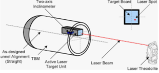
Source : ascelibrary.org, illustration of the laser positioning technic
Magnetic sensors
The principle of magnetic sensor positioning system is to generate a magnetic field with a magnetic field generator located above the surface, this magnetic field acts as a signature that is recognized by the system located into the drilling or boring machine. The drilling machine then knows the deviation from the ideal path and the operator can steer the machine accordingly. This principle is cheap and can be effective only in some specific cases. For instance, if the drilling machine is too far away from the surface (more than few meters), the accuracy of this system is dramatically affected. Depending on the system, steering control and strong electrical currents of the machine can also induce some magnetic perturbations which may affect the magnetic positioning sensor. The optimal accuracy of such a system is 0.4° but if we consider all these perturbations, the real observed accuracy is around several degrees (high voltage wires, surrounding ferro-magnetic materials such as pipes, …).
In addition, it is not always possible to place a magnetic field generator above the surface. For instance, when the tunnel has to cross a river, lake, railways, highways, it is not possible to place the magnetic generator.
These magnetic navigation systems were the first used in the underground market.
Water level
The principle of a water level sensor is to measure a pressure difference of a liquid from a reference point and the measurement point. This difference in pressure is proportional to the difference of height between the navigation point and the reference point. This technic gives a few millimeters accuracy for the height, and there is no drift in time of the value. If the atmospheric pressure changes at the reference point due to changes in weather conditions, it has no impact on the height measurement as the measure is done using a difference of pressure. The drawback is that it requires a long cable to transport the fluid from the reference point to the navigation point and it measures only the height. This technique method can be ideally coupled with other sensors into the navigation system.
Odometer
Odometer sensors measure a distance from a reference point. This distance can be either directly measured with absolute odometer sensors or through sensors that generate ticks periodically every X millimeter. To get the position from the reference point, you need a very accurate heading and pitch. Using dead reckoning technics with an odometer can be very accurate. Unfortunately, it is not always possible to access odometer information.
GNSS input reference
Before the boring or drilling navigation system enters into the ground, it’s often possible to get a GNSS reference point. This point can be used to perform some absolute measurements to initialize the underground navigation system. It can be helpful to initialize the system with initial position (latitude, longitude, altitude and heading). RTK/PPP technique can offer a centimeter level accuracy. Using a double antenna GNSS heading can also provide the heading. The heading coming from a GNSS is noisy but is provided without bias. Using a high-class gyro can reject this noise and initialize the heading of the boring/drilling machine.
Inertial systems
Inertial systems can be used for underground navigation to offer a resilient and performant solution. Three categories are listed below:
IMU (Inertial Measurement Unit)
This unit can output raw data of sensors. This IMU is an assembly of three gyros and three accelerometers. They are calibrated to output synchronized data at a high data rate. Temperature compensation is also performed by the unit.
AHRS (Attitude Heading Reference System)
This system is based on an IMU and runs an algorithm that is able to output heading, roll, pitch, and also accelerations. These data are generally filtered thanks to a Kalman filter. The only required input data is a rough estimation of the latitude to output precisely the heading. The heading accuracy can be better than 0.1° secant latitude RMS (Octans E from iXblue) without the need of a GNSS. This kind of device has no drift in attitude. The pitch and roll accuracy can be as good as 0.01° RMS.
INS (Inertial Navigation System)
In addition to an AHRS device, an INS can output the position and the speed of the drilling/boring platform. An INS device can work in pure inertial mode, but in this case the system will drift over time. The 3D acceleration is integrated once to output the velocity, and the velocity is integrated again to output the position in 3D. Gyroscopes are integrated to output the attitude. Note that when the sensor signal is integrated, the sensor bias error is also integrated, which makes the system drift over time. To reduce this drift, aiding sensors are processed into the Kalman filter’s states of the INS. Therefore, the Kalman filter estimates these biases while aiding sensors are available. This dramatically reduces the error due to biases integration over time. For instance, Phins E from iXblue is able to achieve an accuracy of 0.05° secant latitude RMS in a pure inertial mode once properly aligned.
Post-processing
When drilling a tunnel, if intermediary reference points can be achieved, then using a post-processing technique can dramatically enhance the tunnel survey accuracy. For instance, reference points can be precisely located at the beginning and at the end of the tunnel. As we have shown, when using an INS, the system drifts over time if it is not coupled with aiding sensors. This divergence has a quadratic shape over time (due to the double integration of sensor signal). When we use a forward-backward post-processing analysis, as soon as all raw data sensors have been recorded, it is possible to replay data and reprocess the algorithm reversing the time. In this case, we take benefit of these reference points and they dramatically enhance performance.
Apps, a post-processing software from iXblue
Optical FOG: a solution for high accurate underground navigation
On an inertial navigation system, the short-term heading performance as well as the attitude are given by the accelerometer performance class, but the long-term navigation performance is driven by the gyroscope accuracy.
So, on an underground navigation system, it is crucial to get the best possible gyro.
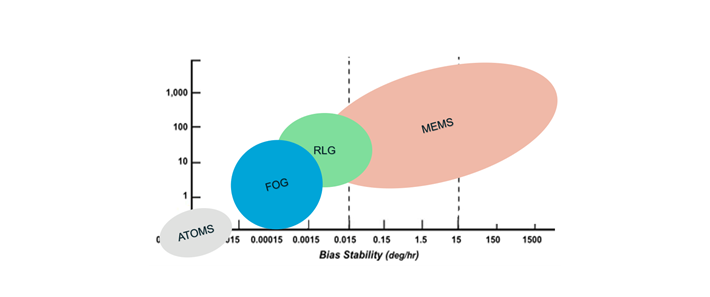
Among all gyroscope technologies: MEMS, RLG, FOG; the FOG (Fiber Optic Gyroscope) offers the most reliable and performance solution available on the commercial market today. See the graphic below where Y axis is the relative scale of performance (relative index: lower is better) versus bias stability shown on the X axis. Today the cold atom technology is mainly reserved for R&D centers as reference units and are too costly and too big to be integrated into a commercial underground navigation system. Note that iXblue recently acquired a company named Muquans specialized in cold atoms to push forward this cutting-edge technology.
FOG is based on the Sagnac effect, as well as the RLG. The Sagnac effect is a quantum relativity effect which produces a phase shift in the light when the gyro is in rotation. On an RLG device, the light makes a loop using mirrors which involved mirrors and very sensitive optoelectrical devices and moving parts. Moreover, into an RLG, in order to avoid the interaction between the light path and the air, the cavity is vacuumed. As this vacuum is not perfect and the quality of the vacuum is decreasing over time, performance may be affected, RLG products have lower MTBF and require a preventive maintenance.
On the opposite, FOG technology doesn’t have any moving parts which makes this technology highly recommended for harsh environment such as the underground navigation (tunneling, mining, drilling and more generally all civil engineering), where shocks and vibrations are part of the day-to-day job.
FOG technology has two variants: open and close loop
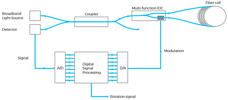
Close loop FOG architecture
The FOG close loop architecture offers the benefit of a high sensibility with an ultra-low noise, whereas the open loop architecture requires less components (no need of extra component for the loop back) but has less performance. For underground applications, end-users are looking for the most accurate solution within a given volume, and therefore the FOG closed loop architecture offers the best solution.
Contrary to RLG (Ring Laser Gyroscope), the FOG has a high sensitivity achieved by a very long fiber length and the surface of the fiber coil. The performance of the product is theoretically unlimited. The larger the diameter is, the better performance are. The evolution of performance over diameter is given by a quadratic curve, whereas the performance over the length is given by a linear relationship.
RLG technology requires electro-moving mirrors due to a lack of sensitivity around the rotation rate of 0°/s. Unfortunately, most of the time, rotation rates are very low for underground applications which makes this technology not relevant for this market.
On the opposite size, FOGs have an excellent sensitivity around 0°/s, and the form factor of the optical coil can be a circle, an octagon, or a special shape done on purpose to fit to the end-user product form factor.
The fast-settling time of iXblue’s products also offers a cost-effective solution and avoid losing time and money when settling up the solution especially in ATEX environment where machines need to be power cycled.
Sensor fusion and ZUPT algorithm
As the INS is already running a Kalman filter, it has the ability to perform an optimal sensor fusion using GNSS, odometer, water level sensor, … This solution offers the best possible performance but needs some work to integrate the sensor model into the INS (only if it is a new one).
If required, the user can also consider an AHRS device and perform the sensor fusion by himself. The sensor fusion is less optimal than in the case of an INS because less Kalman states are tracked into the algorithm, but performance is already very good. This solution offers a flexible solution to most of customers who are looking for a good compromise between performance and integration flexibility.
In addition, the INS algorithm can be adapted to implement ZUPT mode. When the tunneling is not moving the INS is able to detect it and will consider that there is no movement at all. This technique is very efficient as there is no more drift when the machine is not moving. This mode can be set manually or automatically above a determined threshold.
Inertial navigation application with Swissloop Tunneling: Not-a-boring Competition
The Not-a-Boring Competition, hosted by Elon Musk’s The Boring Company, challenges teams from around the world to drill a 30m long and 50cm wide tunnel as quickly and accurately as possible. We, at Swissloop Tunneling, have been selected to be part of the 12 final competitors out of 400+ teams around the world.
The goal of the competition is to have the fastest and most accurate Tunnel Boring Machine (TBM) to reduce tunneling costs and ease the (Hyper)loop concept infrastructure development. At Swissloop Tunneling, we want to push for innovation and our navigation system is crucial towards this goal.
To have the fastest TBM, we earn time in two principal ways:
- Our tunnel is curve-shaped and starts directly from the ground. This enables us to avoid digging and constructing a launching pit for our machine but rather directly start from the surface. Unfortunately, this means we have no line of sight to the back of our machine and all the laser and optic navigation techniques were not suitable to our Navigation design.
- We build the tunnel liner (walls) in real time all around our TBM while digging: this enables continuous tunneling and means we need a precise enough navigation system to carry out digging without inspections/survey checks while beating the accuracy requirements of the competition.
The inertial system of our TBM allows us to have autonomous, fast and reliable localization underground. The performance of our Guidance algorithm is directly correlated to the accuracy of our navigation system and our heading estimation is crucial to avoid and correct for soil drift during tunneling. FOG technology AHRS was particularly suitable and promising for our design, it gives us a very precise attitude estimate without the need of an external infrastructure (by opposition to the Magnetic wire solution) and it also works for hardly accessible, curve-shaped tunnels! For these reasons, we opted for an Octans E.
Designing, building, and testing a Tunnel Boring Machine in less than a year is extremely challenging, even more when entire subsystems of the machine do not follow state of the art industry techniques but rather try to innovate. Therefore, Octans E was a great option for our Navigation system centerpiece: integrating it to our design was almost as easy as plug and play because our TBM already uses Ethernet, and the reliability of the sensor performance saved us a lot of time during prototyping and testing. We could focus our efforts on optimizing our software and the other Navigation sensors.
Finally, the Octans E sensor performance, robustness and easy integration were all important factors to achieve the accuracy our Guidance System requires. Let’s beat the snail!
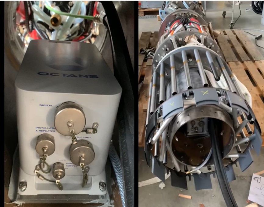 Octans E inside the TBM while mounting
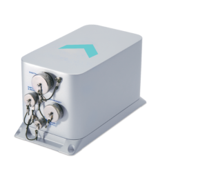
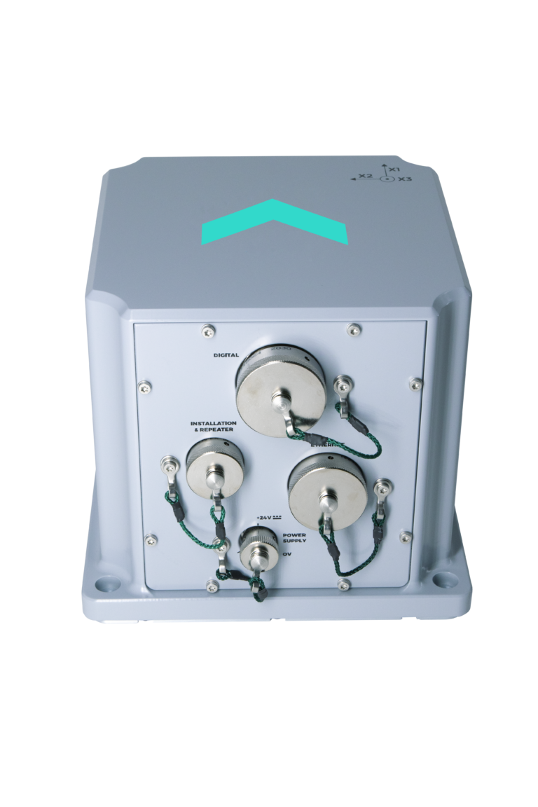
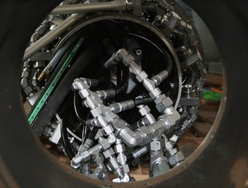 AHRS view when fully assembled (without electrical wires)
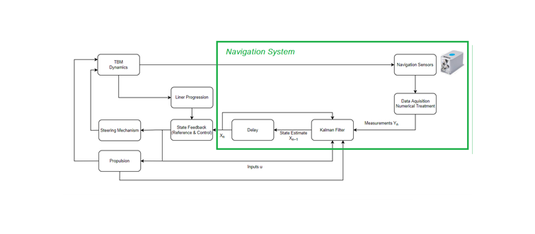
Control Diagram of our TBM
Conclusion
Designing an accurate underground navigation system is very challenging as no GNSS information is available. Each available techniques have advantages and drawbacks. The aim of the sensor fusion is to get the best of each, and an inertial navigation system based on FOG technology offer a very effective solution: performance / cost / reliability / flexibility.


